JetHub E1-PD76-R5-AC microcontroller (v2,v3)

General description
The modular controller JXD-R6-E1ETH (v1) is designed to handle a wide range of tasks in home and industrial automation, as well as monitoring and control of technological processes. The controllers can be used both in local automation systems and as part of distributed systems. The built-in Ethernet communication interface allows the controller to be connected to an existing local area network.
The controller has six power relays with changeover contact (up to 10 A at 250 V AC or 30 V DC) with individual galvanic isolation of outputs, six discrete inputs with group galvanic isolation (common contact COM) for sensors of type dry contact and an input for connecting 1-Wire sensors. For communication, a wired Ethernet 10/100 Mbit/s interface and wireless Wi-Fi and Bluetooth interfaces are provided. The graphic display on the front panel (available depending on configuration) allows displaying the controller state and conveniently configuring controller parameters.
Basic controller functions:
direct control of the low-current load by means of relays.
Polling sensors with discrete output “dry contact”.
Polling 1-Wire sensors.
Measurement of the supply voltage.
Temperature measurement inside the enclosure.
Built-in real-time clock with independent power from a CR1225 battery.
Data transmission via Ethernet, Wi-Fi, and Bluetooth.
Displaying status and configuring parameters using a display with joystick and buttons (depending on configuration).
Расширение периферии внутренними модулями расширения JetHome JXM, устанавливаемыми в корпус контроллера.
Расширение периферии внешними модулями расширения JetHome JXDIO, подключаемыми по внешней шине I2C.
Функции контроллера могут быть расширены с помощью дополнительных модулей расширения: внутренних JetHome JXM, устанавливаемых в корпус контроллера, и внешних JetHome JXDIO, устанавливаемых на DIN-рейку рядом с контроллером. Логика работы контроллера зависит от установленного пользовательского ПО (прошивки).
The DIN-rail enclosure design allows the controller to be conveniently placed in the electrical panel of the house.
Application areas
The controller is designed for local control of electrical loads based on wired sensor states, schedules, and network commands. Typical application scenarios:
Lighting control. Lighting groups connect to relay outputs, and rocker switches, buttons, and motion sensors with an output of the dry contact type - to discrete inputs. Individual galvanic isolation of relay outputs allows switching groups powered from different lines.
Термостат, управление отоплением. Температура контролируется датчиками 1-Wire. Исполнительные устройства - котел, циркуляционные насосы, электроприводы клапанов и коллекторов - подключаются к релейным выходам. Встроенные часы реального времени позволяют реализовать температурные режимы по расписанию.
Управление вентиляцией и климатом. Ступенчатое управление вентиляторами, приводами заслонок и калориферами по состоянию датчиков.
Управление насосным оборудованием и водоснабжением. Управление насосами по сигналам поплавковых датчиков уровня и реле давления с выходом типа “сухой контакт”.
Охранно-технический мониторинг. Опрос датчиков протечки, открытия дверей и окон, концевых выключателей и аварийных контактов оборудования с передачей событий в систему верхнего уровня.
Диспетчеризация инженерного оборудования. Сбор состояния оборудования и передача данных по Ethernet или Wi-Fi, в том числе в качестве удаленного узла ввода-вывода в составе распределенной системы.
Контроллер рассчитан на установку в электрощит и может применяться на объектах:
Квартиры, частные дома и коттеджи.
Офисные и торговые помещения, кафе, гостиницы.
Склады, мастерские, гаражи и паркинги.
Котельные, насосные станции, индивидуальные тепловые пункты.
Теплицы, оранжереи, зимние сады.
Серверные и технические помещения.
Design
The JXD-R6-E1ETH (v2) controller has a modular design.

Controller composition and elements:
Модуль дисплея и джойстика.
Peripheral expansion modules JXM.
Relay terminals
RELAY 1, …RELAY 6.Relay.
Разъем внешней шины I2C (устанавливается опционально).
Terminals of JXM modules for outputting signals from expansion modules.
Discrete input terminals
DIGITAL INPUTS.Terminal
1-WIRE.Power supply terminal
DC IN.Press and hold the FN button on the front panel of the controller.
The processor module power supply is +5V.
Hardware reset button on the front panel of the controller.
USB Type-C console connector
CONSOLEon the front panel of the controller.LED
STATon the front panel of the controller.
Processor and memory
Dual-core microcontroller ESP32-D0WD-V3.
Core frequency up to 240 MHz.
External SPI NOR-Flash with capacity 16 MB.
Built-in microcontroller RAM with capacity 520 KB.
External SPI PSRAM RAM 8 MB (installed depending on configuration).
I2C FRAM 8 KB (installed depending on configuration).
I2C EEPROM 8 KB.
Enclosure
Контроллер JXD-R6-E1ETH (v2) выполнен в корпусе GAINTA D6MG и предназначен для крепления на стандартную DIN-рейку 35мм. Материал корпуса - поликарбонат/ABS UL94-V0. Степень защиты корпуса - IP20 по ГОСТ 14254-2015. Чертеж корпуса GAINTA D6MG
Dimensions and weight
Overall enclosure dimensions - 106.25 x 90.2 x 57.5 mm.
The enclosure width is approximately 6 standard modules for a DIN rail (17.5 mm).
Controller weight in the configuration: processor module, motherboard, display module, without JXM modules - 300 g.
Equipment options
The controller is available in two configuration variants:
JXD-R6-E1ETH - base configuration: without display module, without PSRAM and FRAM memory chips.
JXD-R6-E1ETH-LCD - extended configuration: with display module with joystick and buttons, PSRAM and FRAM memory chips.
Revisions
The JetHub E1-PD76-R5-AC (v2) controller is equipped with an E1-CPU revision 1.2 and a PD76-R5 peripheral board revision 2.0.
Note
The JXD-R6-E1ETH (v1) and JXD-R6-E1ETH (v2) controllers are functionally identical except for the user button: in the JXD-R6-E1ETH (v2) controller, instead of the user button FN there is a hardware reset button.
Also, in the JXD-R6-E1ETH (v2) controller, the Ethernet RJ45 connector has been moved from the front panel to the side wall of the enclosure.
Описание контроллера предыдущей ревизии: JetHub E1-PD76-R5 (v1) microcontroller.
Processor module revisions
v2.0
The user button
FNis missing, instead, a hardware reset button is installedThe
GPIO0pin of the ESP32 microcontroller is used only for standard switching of the microcontroller into bootloader mode
v1.4
Начальная версия модуля
Motherboard revisions
v1.4
Added external I2C bus
Добавлена опциональная возможность установки дополнительного разъема на боковую стенку корпуса для вывода внешней шины I2C
v1.3
Добавлена опциональная возможность установки дополнительного линейного стабилизатора
Добавлены контрольные точки для расширенного тестирования платы
v1.2
Начальная версия платы
Interfaces
Wi-Fi/Bluetooth
The ESP32 microcontroller includes a built-in Wi-Fi/Bluetooth wireless module:
Wi-Fi 802.11b/g/n (2.4 GHz), data transfer rate up to 150 Mbps.
Bluetooth v4.2 BR/EDR with support for BLE specification.
The processor module has a ceramic antenna for the 2.4GHz band. It is possible to connect an external antenna via the U.FL connector, also located on the processor module.
Ethernet
The controller uses an IEEE-802.3-compatible ethernet MAC interface built into the ESP32 microcontroller. Data transfer rates of 10/100 Mbps are supported.
The Ethernet PHY is a LAN8720A chip connected to the ESP32 microcontroller via the RMII interface.
Main characteristics PHY
Data transfer rates of 10 and 100 Mbps are supported.
Half-duplex and full-duplex modes of operation are supported.
The processor module implements a variant of connecting the Ethernet PHY chip without using an additional crystal oscillator or generator.
The 50 MHz clock pulses required for the Ethernet PHY chip are generated by the ESP32 microcontroller itself.
Wiring diagram
The Ethernet PHY chip is connected to the following pins of the ESP32 microcontroller:
ESP32 output |
Function |
|---|---|
GPIO25 |
ETH_RXD0 |
GPIO26 |
ETH_RXD1 |
GPIO27 |
ETH_CRS_DV |
GPIO19 |
ETH_TXD0 |
GPIO22 |
ETH_TXD1 |
GPIO21 |
ETH_TXDEN |
GPIO23 |
ETH_MDC |
GPIO18 |
ETH_MDIO |
GPIO17 |
50MHZ CLK OUT |
GPIO15 |
ETH_RESET |
The GPIO15 pin of the ESP32 microcontroller is used for hardware reset of the Ethernet PHY chip: logic level 0 - chip reset, logic level 1 - operating mode.
External periphery
Display
A display module with a joystick and buttons can be installed on the front panel of the controller. The display allows you to show the state of the controller, as well as configure the controller parameters. The information displayed on the display and the assignment of the display buttons depend on the software installed on the controller.
Note
The display module is installed depending on the configuration of the controller.
The display module has a monochrome OLED screen with a 1.3-inch diagonal and a resolution of 128x64 pixels. The screen is connected to the internal I2C bus, the address of the screen on the internal I2C bus is 0x3C.
The display driver is SH1106.
The display module is connected to the processor module using a four-wire cable with Micro JST connectors with a contact pitch of 1.25mm.
Pin assignment of the display module connector:
Contact number |
Destination |
Description |
|---|---|---|
1 |
I2C SCL |
Clock line of the internal I2C bus |
2 |
I2C SDA |
Data line of the internal I2C bus |
3 |
+3,3V |
Power supply of the display module +3,3V |
4 |
GND |
Common wire |
Display module port expander
The display module has a port expander chip PCA9535 connected to the internal I2C bus.
Port expander chip address on the internal I2C bus - 0x24.
The port expander chip is used to read the states of the joystick and buttons.
Used ports of the display module expander
Port |
Function |
Description |
|---|---|---|
8 |
UP |
Joystick contact “Up” |
9 |
DOWN |
Joystick contact “Down” |
10 |
LEFT |
Joystick contact “Left” |
11 |
RIGHT |
Joystick contact “Right” |
12 |
ENTER |
Central contact of the joystick “Enter/OK” |
13 |
HOME |
Кнопка “Домой/Начало” |
14 |
BACK |
Кнопка “Назад/Отмена” |
The remaining ports of the extender chip are not used.
The state of the optional user button for module revision 1.1 is determined by the following logic levels at the port expander input: 0 - button closed (pressed), 1 - button open. This button is not used in subsequent revisions of the processor module.
Relay
The motherboard contains 6 discrete relay outputs with output type Changeover contact and the following characteristics:
Максимальный коммутируемый ток - 10А для резистивной нагрузки
Maximum switching voltage - 250V AC or 30V DC.
Электрический ресурс реле - 100 000 переключений при максимальной нагрузке.
Релейные выходы имеют индивидуальную гальваническую изоляцию: выходы каждого реле гальванически изолированы друг от друга.
Опционально контроллер может комплектоваться реле с усиленными контактами, выдерживающими пусковой ток до 80А в течение 20 мс.
Warning
Реле не имеют защиты от перегрузки и перегрева. При превышении номинальных характеристик реле и устройство могут быть повреждены.
Relay outputs are brought out to three-pin screw terminals RELAY 1, … RELAY 6 with a contact pitch of 5 mm.
Перекидной контакт позволяет использовать релейный выход как нормально разомкнутый NO, так и нормально замкнутый NC, а также переключать нагрузку между двумя цепями. Индивидуальная гальваническая изоляция выходов позволяет коммутировать нагрузки, запитанные от разных линий или от разных источников питания, независимо друг от друга.
Управление реле осуществляется через расширитель портов материнской платы (см. раздел Расширители портов GPIO).
Условная схема релейного выхода и возможный вариант подключения нагрузки (R1 и R2 на схеме) к релейному выходу контроллера:

Discrete inputs
The controller motherboard contains 6 discrete inputs for connecting sensors of type Dry Contact, brought out to two external four-pin screw terminals DIGITAL INPUTS with a contact pitch of 3.5 mm.
Дискретные входы имеют групповую гальваническую изоляцию: входы изолированы от остальных элементов устройства, но не изолированы между собой и имеют один общий контакт COM. Замыкание дискретных входов DIGITAL INPUT 1, … DIGITAL INPUT 6 должно производиться на общий контакт COM, находящийся на клеммах дискретных входов. Соединять вывод COM с выводом GND на устройстве не нужно.
Для дискретных входов предусмотрена аппаратная защита от дребезга контактов с помощью триггеров Шмитта. Напряжение внутренней “подтяжки” входов около 5В. Ток дискретного входа в замкнутом состоянии - около 5мА.
Состояние дискретных входов считывается через расширитель портов материнской платы (см. раздел Расширители портов GPIO).
Controller discrete input wiring diagram and connection of sensors with a “dry contact” output to the discrete input terminal:

К дискретным входам могут быть подключены устройства с транзисторным выходом n-p-n типа, выполненным по схеме “открытый коллектор”. Условная схема подключения датчиков с транзисторным выходом n-p-n типа:

Purpose of the discrete input terminal contacts:
Contact number |
Destination |
Description |
|---|---|---|
1 |
COM |
Binary input terminals |
2 |
INPUT 1 |
Discrete input 1 |
3 |
INPUT 2 |
Discrete input 2 |
4 |
INPUT 3 |
Discrete input 3 |
Нумерация контактов на клемме слева направо. В скобках указаны номера дискретных входов для второй клеммы дискретных входов.
Warning
Be careful when connecting the digital inputs. Do not allow voltage to be applied to the digital inputs, there are pull-up resistors to 5V on the board.
1-Wire
The controller provides the ability to connect external sensors via the 1-Wire bus.
Шина 1-Wire реализована на микросхеме преобразователя I2C в 1-Wire DS2482S-100, установленной на материнской плате.
Address of the DS2482S-100 microchip on the internal I2C bus - 0x18.
Формирование временных диаграмм шины 1-Wire выполняется преобразователем аппаратно, без участия микроконтроллера.
The board has a pull-up resistor on the 1-Wire data line, no additional external pull-up resistors are required. It is recommended to connect 1-Wire sensors using a three-wire scheme (including the power line).
Maximum output current from the power supply terminal 1-WIRE - 0.5 A.
1-Wire connector
For the 1-WIRE terminal, a three-pin screw terminal with a contact pitch of 3,5mm is used.
Pin assignment:
Contact number |
Destination |
Description |
|---|---|---|
1 |
GND |
Common 1-Wire |
2 |
IO4 |
1-Wire data bus |
3 |
+5V |
Power output +5V (for powering external devices 1-Wire) |
Нумерация выводов на клемме 1-WIRE слева направо.
Internal I2C bus
Note
The external I2C bus is available starting with revision 1.4 of the motherboard.
Внешняя шина I2C предназначена для подключения внешних модулей расширения JetHome JXDIO, устанавливаемых на DIN-рейку рядом с контроллером. Шина и сопровождающий ее сигнал прерывания выведены на следующие выводы микроконтроллера:
ESP32 output |
Destination |
|---|---|
GPIO1 |
I2C2 SCL |
GPIO1 |
I2C2 SDA |
GPIO36 |
MOD_INT |
Внешняя шина I2C независима от внутренней шины I2C контроллера: шины используют разные выводы микроконтроллера, поэтому адреса устройств на внешней шине не конфликтуют с адресами внутренней периферии контроллера.
На линиях внешней шины I2C на материнской плате установлены подтягивающие резисторы.
Рекомендованная частота шины: 100кГц (Standard mode) или 400кГц (Fast mode).
Разъем внешней шины I2C
Шина выводится на опциональный двухрядный штыревой разъем 2x5 контактов с шагом контактов 2,54мм, устанавливаемый на боковой стенке корпуса контроллера.
Назначение выводов разъема внешней шины I2C:
Contact |
Destination |
|---|---|
1 |
DC OUT |
2 |
GND |
3 |
I2C2 SCL |
4 |
I2C2 SDA |
5 |
MOD_INT |
6 |
MOD_INT |
7 |
I2C2 SDA |
8 |
I2C2 SCL |
9 |
GND |
10 |
DC OUT |
Назначение выводов симметрично относительно середины разъема: контакты 1 … 5
повторяются контактами 10 … 6.
На контакты DC OUT выводится питающее напряжение контроллера: напряжение с клеммы
DC IN при питании контроллера от внешней клеммы или напряжение Passive PoE
при питании контроллера от разъема Ethernet.
Максимальный ток питающего напряжения через разъем внешней шины I2C - 1А. Это необходимо учитывать при питании модулей расширения от контроллера.
Контакты INT объединены с контактом INT разъема процессорного модуля по схеме
“монтажное ИЛИ” и предназначены для подачи сигнала прерывания от модуля расширения
к процессорному модулю. Подтягивающий резистор линии установлен на материнской плате.
The inner periphery
Память
FLASH
The processor module has a SPI NOR-Flash memory chip with a capacity of 16 MB. The Flash memory chip is connected to the following pins of the ESP32 microcontroller:
ESP32 output |
Destination |
|---|---|
GPIO6 |
QSPI CLK |
GPIO7 |
QSPI IO1/DO |
GPIO8 |
QSPI IO0/DI |
GPIO9 |
QSPI IO3/HOLD |
GPIO10 |
QSPI IO2/WP |
GPIO11 |
FLASH CS |
PSRAM
Note
The PSRAM memory chip is installed depending on the controller configuration.
The processor module has a SPI PSRAM memory chip with a capacity of 8 MB. The memory chip is connected to the following pins of the ESP32 microcontroller:
ESP32 output |
Destination |
|---|---|
GPIO6 |
QSPI CLK |
GPIO7 |
QSPI IO1/DO |
GPIO8 |
QSPI IO0/DI |
GPIO9 |
QSPI IO3/HOLD |
GPIO10 |
QSPI IO2/WP |
GPIO1 |
PSRAM CS |
Internal I2C bus
The I2C bus is used to connect various peripheral devices and is routed to the following pins of the microcontroller:
ESP32 output |
Destination |
|---|---|
GPIO4 |
I2C SCL |
GPIO5 |
I2C SDA |
Recommended bus frequency: 100kHz (Standard mode) or 400kHz (Fast mode). These modes are supported by most peripheral chips.
The I2C bus is also terminated on a 40-pin expansion slot and is used to connect external peripherals.
EEPROM
Processor module EEPROM
The processor module has a non-volatile EEPROM memory chip AT24C64 (or equivalent) of 64Kbit (8 KBytes).
The purpose of this memory is to store the hardware configuration of the processor module.
The address of the memory chip on the I2C bus is 0x54.
EEPROM of the peripheral board
A EEPROM non-volatile memory chip AT24C64 (or analog) of 64Kbit (8 KByte) is installed on the peripheral board.
The purpose of this memory is to store the hardware configuration of the motherboard or other user data (depends on installed software).
The address of the memory chip on the I2C bus is 0x56.
FRAM
Note
The FRAM memory chip is installed depending on the controller configuration.
The processor module has a non-volatile EEPROM memory chip AT24C64 (or equivalent) of 64Kbit (8 KBytes).
Данная микросхема выдерживает большое количество циклов перезаписи. Назначение данной памяти - хранение часто меняющихся данных: состояние параметров контроллера и других данных пользователя.
The address of the memory chip on the I2C bus is 0x54.
Real Time Clock (RTC)
The processor module has a real-time clock chip PCF8563 (or analog).
The chip is connected to the internal I2C bus of the module. The address of the chip on the I2C bus is 0x51.
To power the RTC, a CR1225 coin cell battery with a voltage of 3V is installed on the processor module board.
See also
Reading data from a temperature sensor
The processor module has a real-time clock chip PCF8563 (or analog).
The chip is connected to the internal I2C bus of the module. The address of the chip on the I2C bus is 0x51.
Power supply indication
Процессорный модуль позволяет производить измерение входных питающих напряжений. Измерение производится встроенным АЦП микроконтроллера ESP32 с предварительным делителем напряжения с коэффициентом 1:32. Точность измерения напряжения около 3%.
Two voltage measurement channels are provided:
Voltage on the DC IN power terminal. The
GPIO35input is used - channelADC_CH7of the ESP32 microcontroller.Passive PoE supply voltage on the RJ45 Ethernet connector. The
GPIO37input is used - channelADC_CH1of the ESP32 microcontroller.
GPIO port expanders
Peripheral board port expander
The port expander chip is used to control relays and read the status of the controller’s digital inputs.
A PCA9535 chip connected to the internal I2C bus is installed on the motherboard as a port expander.
The address of the memory chip on the I2C bus is 0x54.
Выход прерывания микросхемы расширителя портов подключен к контакту INT разъема
процессорного модуля - выводу GPIO36 микроконтроллера ESP32. Использование сигнала
прерывания опционально: состояние портов расширителя может опрашиваться по шине I2C.
Peripheral board expander ports in use
Port |
Function |
Description |
|---|---|---|
0 |
RELAY 1 |
Relay 1 control output |
1 |
RELAY 2 |
Relay 2 control output |
2 |
RELAY 3 |
Relay control output 3 |
3 |
RELAY 4 |
Relay control output 4 |
4 |
RELAY 5 |
Relay control output 5 |
5 |
RELAY 1 |
Relay 1 control output |
6 |
RESET |
Hardware reset output of module JXM1 |
7 |
RESET |
Output. Interrupt from the JXM module |
8 |
INPUT 1 |
Discrete input 1 |
9 |
INPUT 2 |
Discrete input 2 |
10 |
INPUT 3 |
Discrete input 3 |
11 |
INPUT 4 |
Discrete input 4 |
12 |
INPUT 5 |
Discrete input 5 |
13 |
INPUT 6 |
Discrete input 6 |
14 |
RESET |
Hardware reset output of module JXM2 |
15 |
RESET |
Output. Interrupt from the JXM module |
Relay control logic for peripheral board revision 3.0: logic level 0 - relay off, logic level 1 - relay on. By default, after power-up the port expander outputs are set to the logic level 0 (relays are off).
The states of the digital input are determined by the following logic levels at the port expander inputs: 0 - input open, 1 - input closed.
Internal connectors
Processor module revisions
Для подключения процессорного модуля JXD-CPU-E1ETH к материнской плате используется двухрядный штырьевой разъем 32 контакта с шагом контактов 2,54мм. Часть контактов разъема зарезервирована для других целей и не используется в данном процессорном модуле.
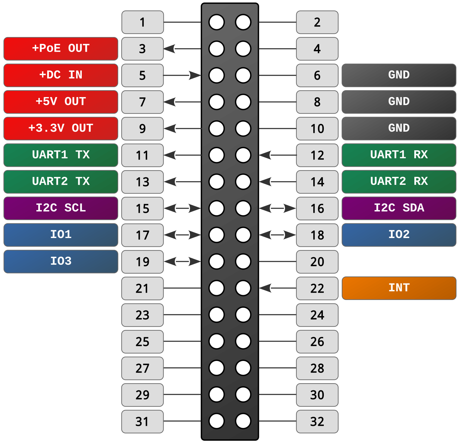
Contact |
Destination |
Description |
|---|---|---|
1 |
Not used. |
|
2 |
Not used. |
|
3 |
+3.3V |
Passive PoE voltage output from the Ethernet connector of the processor module. |
4 |
Not used. |
|
5 |
+3.3V |
Supply voltage input from the motherboard. |
6 |
GND |
General. |
7 |
+3.3V |
5V voltage output from the processor module. |
8 |
GND |
General. |
9 |
+3.3V |
3.3V voltage output from the processor module. |
10 |
GND |
General. |
11 |
UART1_TX |
UART1_TX line. Connected to the IO33 pin of the ESP32. |
12 |
UART1_RX |
UART1_TX line. Connected to the IO33 pin of the ESP32. |
13 |
UART2_TX |
UART2_TX line. Connected to the IO2 pin of the ESP32. |
14 |
UART2_RX |
UART2_TX line. Connected to the IO2 pin of the ESP32. |
15 |
I2C_SCL |
I2C_SCK line. Connected to the IO4 pin of the ESP32. |
16 |
I2C_SDA |
I2C_SDA line. Connected to the IO5 pin of the ESP32. |
17 |
IO19 |
SPI_MOSI line. Connected to pin IO13 of the ESP32. |
18 |
IO2 |
SPI_MISO line. Connected to the IO12 pin of the ESP32. |
19 |
IO23 |
SPI_CLK line. Connected to pin IO14 of the ESP32. |
20 |
Not used. |
|
21 |
Not used. |
|
22 |
MOD_INT |
Вход внешнего прерывания от материнской платы к процессорному модулю. Подключен к выводу GPIO36 ESP32. |
23 |
Not used. |
|
24 |
Not used. |
|
25 |
Not used. |
|
26 |
Not used. |
|
27 |
Not used. |
|
28 |
Not used. |
|
29 |
Not used. |
|
30 |
Not used. |
|
31 |
Not used. |
|
32 |
Not used. |
40-pin connector on the motherboard
Для подключения процессорного модуля к материнской плате JXD-D6-R6 используется двухрядный штырьевой разъем 32 контакта с шагом контактов 2,54мм. Часть контактов данного разъема зарезервирована для других целей и не используется в данной материнской плате.

Интерфейсы UART процессорного модуля выведены на разъемы модулей расширения:
UART1 - на разъем JXM1, UART2 - на разъем JXM2.
Contact |
Destination |
Description |
|---|---|---|
1 |
Not used. |
|
2 |
Not used. |
|
3 |
+3.3V |
Passive PoE voltage input from the Ethernet connector of the processor module. |
4 |
Not used. |
|
5 |
+3.3V |
Supply voltage output from the motherboard. |
6 |
GND |
General. |
7 |
+3.3V |
5V voltage input from the processor module. |
8 |
GND |
General. |
9 |
+3.3V |
3.3V voltage input from the processor module. |
10 |
GND |
General. |
11 |
UART1_TX |
Interrupt input from the GPIO port expander of the CPU module. Output to the peripheral connector. |
12 |
UART1_RX |
Interrupt input from the GPIO port expander of the CPU module. Output to the peripheral connector. |
13 |
UART2_TX |
Interrupt input from the GPIO port expander of the CPU module. Output to the peripheral connector. |
14 |
UART2_RX |
Interrupt input from the GPIO port expander of the CPU module. Output to the peripheral connector. |
15 |
I2C_SCL |
This peripheral is available starting with motherboard revision v3.5. |
16 |
I2C_SDA |
This peripheral is available starting with motherboard revision v3.5. |
17 |
I2C_SCL |
This peripheral is available starting with motherboard revision v3.5. |
18 |
Not used. |
|
19 |
I2C_SDA |
This peripheral is available starting with motherboard revision v3.5. |
20 |
Not used. |
|
21 |
Not used. |
|
22 |
INT OUT |
Выход прерывания от расширителя портов материнской платы. На плате установлен подтягивающий резистор. |
23 |
Not used. |
|
24 |
Not used. |
|
25 |
Not used. |
|
26 |
Not used. |
|
27 |
Not used. |
|
28 |
Not used. |
|
29 |
Not used. |
|
30 |
Not used. |
|
31 |
Not used. |
|
32 |
Not used. |
40-pin connector on the motherboard
Для подключения модулей расширения JXM к материнской плате используются два двухрядных штырьевых разъема: 6 контактов JXM IO и 4 контакта JXM EXT с шагом контактов 2,54мм. Разъем 6 контактов JXM IO используется для питания модуля и подключения модуля к процессору по интерфейсу UART. Разъем 4 контакта JXM EXT используется для вывода сигналов с модуля расширения на внешнюю четырехконтактную винтовую клемму.

Contact |
Destination |
Description |
|---|---|---|
1 |
+3.3V |
5V output for powering JXM modules. |
2 |
GND |
General. |
3 |
UART1_RX |
Interrupt output from the module (low logic level). |
4 |
UART1_TX |
Interrupt input from the GPIO port expander of the CPU module. Output to the peripheral connector. |
5 |
RESET |
The circuit must provide a mounted OR - open collector output. |
6 |
MODE1 = 0 |
The circuit must provide a mounted OR - open collector output. |

Contact |
Destination |
Description |
|---|---|---|
1 |
IO19 |
It is connected to an external terminal. |
2 |
IO4 |
It is connected to an external terminal. |
3 |
IO2 |
It is connected to an external terminal. |
4 |
IO23 |
It is connected to an external terminal. |
В качестве внешних клемм для модулей JXM1 и JXM2 используются винтовые клеммы с шагом контактов 3,5мм. Нумерация контактов внешней винтовой клеммы JXM слева направо.
Выводы разъемов JXM IO слотов JXM1 и JXM2 подключены к разным выводам
микроконтроллера и к разным портам расширителя портов материнской платы (адрес 0x22):
Pin assignment of the connector JXM IO of slot JXM1:
Contact |
Destination |
Connection |
|---|---|---|
1 |
+3.3V |
Module power supply +5V |
2 |
GND |
Common wire |
3 |
UART1_RX |
Вывод |
4 |
UART1_TX |
Вывод |
5 |
RESET |
Port |
6 |
MODE1 = 0 |
Port |
Pin assignment of the connector JXM IO slot JXM2:
Contact |
Destination |
Connection |
|---|---|---|
1 |
+3.3V |
Module power supply +5V |
2 |
GND |
Common wire |
3 |
UART1_RX |
Вывод |
4 |
UART1_TX |
Вывод |
5 |
RESET |
Port |
6 |
MODE1 = 0 |
Port |
Note
Разъем JXM EXT одинаков для обоих слотов: его выводы не подключены к микроконтроллеру
и выведены на внешнюю винтовую клемму соответствующего модуля.
Console
The processor module board has a USB-UART interface converter on the microchip CP2102, and a MicroUSB connector on the front panel of the controller.
For console connection, the GPIO1 - UART0_TX and GPIO3 - UART0_RX pins of the ESP32 microcontroller are used.
С помощью сигналов RTS и DTR интерфейса UART осуществляется автоматический сброс микроконтроллера и переключение его в режим загрузки ПО. Для этого можно использовать стандартные утилиты для прошивки микроконтроллеров ESP32.
Power
The following power supply options are available:
From an external stabilized DC power source through the external screw red terminal with 3.5 mm contact pitch on the motherboard.
Note
Recommended (rated) input voltage range 12V to 48V.
Maximum allowable input voltage 36V.
Via technology Passive PoE via the Ethernet port connector.
Note
Recommended rated input supply voltage Passive PoE - from 12V to 24V.
Maximum allowable input voltage 36V.
The polarity of the connection does not matter. Recommended power supply scheme: “+” of the power supply to pins 4 and 5, “-” of the power supply to pins 7 and 8 of the Ethernet connector.
Необходимо учитывать падение напряжения на длинных линиях и выбирать источник питания с большим выходным напряжением. Для питания контроллера по технологии Passive PoE рекомендуется использовать источник питания с напряжением 24В.
Note
If power is applied to both the external terminal and the Ethernet connector at the same time, power will be supplied from a high voltage source. It is recommended to use one of the power supply options.
Потребляемая мощность контроллера без дополнительных модулей JXM до 3Вт. При установке дополнительных модулей расширения потребляемая контроллером мощность может существенно возрасти. Это необходимо учитывать при выборе источника питания для контроллера.
To power the controller, it is recommended to use a stabilized DC power supply with a power of at least 5W.
При использовании дополнительных модулей JXM и питании внешних устройств и датчиков
от вывода +5V клеммы 1-WIRE рекомендуется использовать блок питания мощностью
не менее 10Вт.
Warning
There is no galvanic isolation of the power supply circuits in the controller.
Software
See also
Officially supported software:
ESPHome - ESP32 firmware to work with Home Assistant.
ESP-IDF - official SDK from Espressif for development on ESP32.
Note
It is also possible to use any other software for ESP32: Tasmota, Arduino and others.
Controller firmware
The ESP32 microcontroller has the ability to flash over a dedicated UART0 interface (pins IO34 and IO35 of the ESP32 module).
For flashing it is enough to connect the processor module board to the computer through the USB interface, through the MicroUSB connector on the front panel of the controller.
Note
When using standard tools for flashing ESP32 microcontrollers the switch to the bootloader mode is made automatically when flashing.
Note
The processor module can be powered from the MicroUSB connector during flashing.
This will not supply power to the lower controller board.
Safety precautions
Во время эксплуатации и технического обслуживания устройства следует соблюдать требования ГОСТ 12.3.019-80, «Правил эксплуатации электроустановок потребителей» и «Правил охраны труда при эксплуатации электроустановок потребителей».
Любые подключения к прибору и работы по его техническому обслуживанию следует производить только при отключенном питании устройства и подключенных к нему исполнительных механизмов.
Физический доступ к устройству при монтаже и обслуживании должен быть разрешен только квалифицированному обслуживающему персоналу.
Не допускается попадание влаги на контакты выходных соединителей и внутренние элементы устройства.
Устройство запрещено использовать при наличии в атмосфере кислот, щелочей, масел и иных агрессивных веществ.
Устройство не предназначено для использования на объектах, потенциально представляющих опасность для жизни и здоровья окружающих.
Если устройство имеет интерфейс Ethernet, не допускается подключать его к локальной сети с выходом в сеть Internet без обеспечения надежных средств межсетевой защиты.
Mounting
Note
При монтаже устройства силовое оборудование в шкафу должно быть обесточено.
The unit can be installed in an electrical equipment cabinet or other location, where it must be protected from moisture, dirt and foreign objects, as well as vibration-free.
Note
For better cooling of the internal components, the housing should be installed in an upright position.
To install it, you have to:
Make sure there is enough space to connect the device and run the wires.
Securely fasten the unit to the DIN rail or to a vertical surface with screws.
To remove it from the DIN-rail you should:
Insert the tip of a screwdriver into the latch eyelet.
Press the latch down.
Отвести устройство от DIN-рейки.
Operating conditions
Ambient temperature: 0..+40 С.
Relative humidity up to 80% without condensation.
Closed explosion-proof rooms without aggressive vapors and gases.
Устойчивость к климатическим воздействиям соответствует категории УХЛ4 по ГОСТ 15150-69.
Wiring recommendations
Для обеспечения надежности электрических соединений рекомендуется использовать медные многожильные кабели. Концы кабелей следует зачистить, потом залудить их или использовать кабельные наконечники. Жилы кабелей следует зачищать так, чтобы их оголенные концы после подключения к устройству не выступали за пределы клеммника.
General requirements for connection lines:
When laying the cables, the communication lines that connect the device to the sensors or other devices should be separated into separate routes, and located separately from power cables and cables that cause high-frequency and pulse interference.
Для защиты входов устройства от влияния электромагнитных помех линии связи следует экранировать. В качестве экранов могут быть использованы специальные кабели с экранирующими оплетками.
В линии питания устройства рекомендуется устанавливать фильтры сетевых помех.
In the case of controlling power equipment, it is recommended that spark-quenching filters be installed on the switching line of this equipment.
Limitations
Warning
The device is not intended for use in facilities potentially endangering the life and health of others, as well as life support systems and other critical systems.
Useful Links
The ESP32 Pin list is a list of ESP32 pins and their functions.